Why has Pear adopted fieldbus?
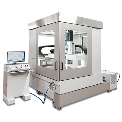
Machine tools have become increasingly complex, with a corresponding increase in on-board wiring.
The field bus allows, by means of data concentrators spread on board the machine, to significantly reduce the electrical connections to the CNC as well as allowing a whole set of diagnostic services, even remotely, otherwise not possible.
A bit of history
Historically and logically, there are two elements that come into play to drive a numerical control machine:
a) The numerical control. This is the “noble” part of the electronics, the one that interpolates the axes and moves them at the programmed speed.
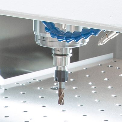
b) The machine interface. In a numerical control machine there is more than just moving the axes; just imagine for a moment all the complications involved in replacing the tool. Or, in machines of more recent construction, what it takes to automatically change the workpiece. So there are a whole series of solenoid valves, cylinders but also secondary axes to be driven. By secondary axes we mean axes that are simply positioned at predetermined dimensions. The functions of the machine interface to the machine tool were carried out by an “infinite” series of relays that were wired appropriately to carry out the intended functions. If it was necessary to modify one or more machine logic functions, it was necessary to take the screwdriver and modify the wiring of the various relays related to that function.
End of the 60s
The first PLCs (Programmable Logic Controllers) appeared on the market. They were programmed by having a perforated tape read (perhaps there are still those who remember the old teletypewriters used to send Telex).
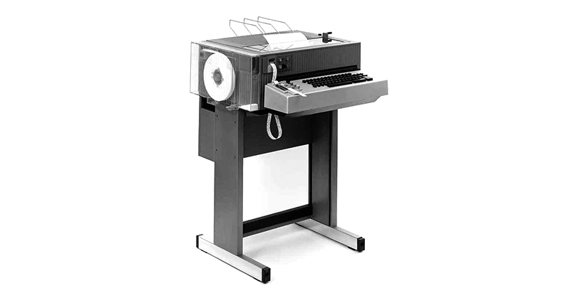
To modify the machine logic it was sufficient to modify the text that contained the instructions and perforate a tape. No screwdriver! It was already a great step forward.
Early 70’s
The manufacturer of Cn ECS (Florence) was among the first, if not the first, to have the intuition to incorporate the PLC directly into the Cn while remaining a separate logic unit. The machine builder could then modify the logic of the machine simply by using the monitor (at that time tiny). This architecture has remained unchanged until today regardless of the Cn manufacturer chosen and will probably remain in the vast majority of machine tools for many years to come. It must be pointed out that there may be Cn’s where the writing of machine logic is not allowed by the machine manufacturer. For technical and/or commercial reasons the machine logic is written only by the Cn manufacturer. In this regard, it should be noted that incorrectly writing one or more lines of machine logic may cause serious damage to the machine. This may also be a reason why some Cn manufacturers do not allow free access to their programmable logic. As Pear we have always, as a business choice, written our machine logic in-house. There are numerous pieces of current production machine logic whose writing dates back over 30 years.
What about PLCs?
At first glance, since PLCs have been incorporated into the CN, you might think that they have disappeared from the market. Nothing could be more false!
Here, however, an important clarification must be made. There are objectively on the market a certain number of numerical control machines in which the machine logic is written on a separate PLC. There may be various reasons that have pushed these manufacturers to follow this configuration. For example, to be able to offer several CNCs from different manufacturers and to be able to write all the machine logic software only once on these external PLCs. In our opinion, these choices are technically wrong, especially since remote assistance via Internet has become available. The machine manufacturer must have remote access to all machine functions and be able to modify them directly. Something that would not be possible with a separate PLC.
Returning to PLCs, not only have they not disappeared, but they have undergone enormous development. Talking about industrial automation, the world of CNC is really a small thing. Surely on television you have seen these mega automatic warehouses that automatically sort hundreds of orders per hour. Just imagine the complexity of the electrical connections behind these systems. But even a simple (so to speak!) beverage or snack vending machine has top-notch electronics behind it.
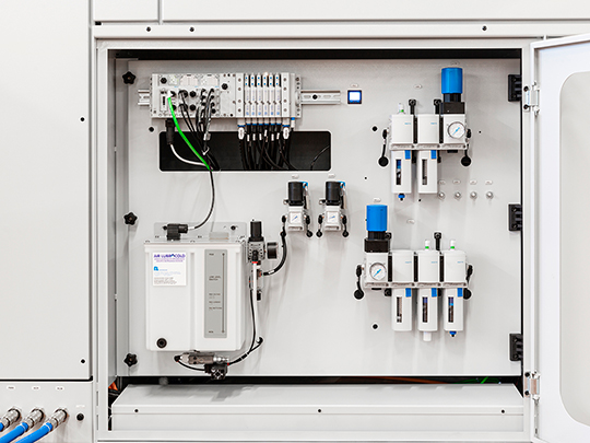
Having to connect hundreds/thousands of electrical connections physically very far from each other they started to think (this at the end of the 90’s) but why don’t we divide these mega electrical systems in many “nodes” and connect these known among them through a network? At that time corporate networks (LANs) were already widely used and so it was easy to imagine something similar. Dividing the cabling in this way would have made it certainly cheaper (which is not so important) and above all more flexible. Let’s imagine in an automatic warehouse, if at a certain point sensors were to be added, the problem that would arise from having to carry these wires to the centralized electrical cabinet. If, on the other hand, these extra wires were to be wired only locally, it would become a marginal problem. In order to carry out these new functions, the company’s network was not used, but a “field bus” made for this purpose was used (in my opinion, rightly so).
And here all hell broke loose. Different field buses, with different specifications, some proprietary and some open. When there is an innovation it is also logical that there may be different ideas and interests. But now over 20 years have passed and slowly the fog that was there has largely dissolved.
How have NC manufacturers reacted to the emergence of fieldbuses?
They have tended to ignore the problem. As complex as a machine tool may be, it is not as complex as, say, an automated package sorting plant.
All the input/output boards of a CNC are built directly by the CNC manufacturer. They are relatively speaking very cheap and super reliable boards (this feature is very important in the machine tool world). If there is a problem, the person responsible for the problem will be immediately identified, i.e. the Cn manufacturer.
The fieldbus presupposes the presence of several manufacturers, from a system point of view it is certainly a much more complex architecture. In case of malfunctions it would be immediately necessary to identify the responsible of such malfunctions.
But implementing the fieldbus also at the machine tool level brings significant advantages. First of all, greater flexibility in adapting the machine to the specific needs of the customer, which have become and will become increasingly variable. In practice, every machine tends to become more and more “one off”. In remote assistance then (from the Internet) it is possible to have much more data. The operation of a single solenoid valve, for example, can be tested remotely. Should it be necessary to add other components after delivery of the machine, this would also become much easier.